[F4] Neopixel driver using hardware timers

What are you developing?
flyboy74
Posts: 31
Joined: Fri Jan 03, 2020 10:12 am

Re: [F4] Neopixel driver using hardware timers

Post by flyboy74 »

ozcar wrote: Tue May 05, 2020 4:01 am
I don't see anything there to say that you must have the total time for high + low different for zero and one bits?
I will have to put my MCU on back on the scope and check the signal train timing and might need to updat my code slightly to work better.

From that link in last post
Capture.JPG
Capture.JPG (52.93 KiB) Viewed 5200 times
You can see that a 1 and a 0 have different high times but the same low times making for a different total time total times for a 1 and a 0. There are other LEDs around like too.
ozcar
Posts: 144
Joined: Wed Apr 29, 2020 9:07 pm
Answers: 5

Re: [F4] Neopixel driver using hardware timers

Post by ozcar »

flyboy74 wrote: Tue May 05, 2020 11:09 am ...
You can see that a 1 and a 0 have different high times but the same low times making for a different total time total times for a 1 and a 0. There are other LEDs around like too.
Yes, they give the same range for the zero and one low times, but they cover a wide enough range that there is no need for the total (H + L) to be different. Probably makes sense to keep the total time down, while avoiding the extreme ends of the ranges. So what is wrong having say both the zero and one highs smack in the middle of the allowed ranges, with zero bit = 375H + 875L and one bit = 875H + 375L ?
ag123
Posts: 1668
Joined: Thu Dec 19, 2019 5:30 am
Answers: 25

Re: [F4] Neopixel driver using hardware timers

Post by ag123 »

+1 @flyboy74
this is really nice, i've wanted to mess with timers doing something basically this & you have been there done that :D
i think playing with ARR is a good way, of course another way may be to play with the output compare registers which would enable messing in 4 channels.
but that can be a lot harder than simply doing ARR as the period between the 1 code and low code are different.
i.e. it is useless to keep timers at the same frequency to try to send different 1 and 0 codes
i'm not too sure if between each 1 or 0 code (symbol) if we'd need to insert that 'frame unit' if that is a code separator?
the different period alone would be enough to just stick with ARR than play with output compare as those are intended for duty cycles but at a same base frequency
ozcar
Posts: 144
Joined: Wed Apr 29, 2020 9:07 pm
Answers: 5

Re: [F4] Neopixel driver using hardware timers

Post by ozcar »

ag123 wrote: Tue May 05, 2020 4:31 pm ...
i'm not too sure if between each 1 or 0 code (symbol) if we'd need to insert that 'frame unit' if that is a code separator?
There is no need for any separation between the bits, but there is a need to have a gap (absence of any pulses) when data for all the LEDs has been transmitted. That end-of-data indicator has to be longer than a specified minimum (to confuse things somewhat, that particular data sheet on one page says that the minimum time for that is 300 microseconds, and on another page says 250 microseconds). They generally call this long gap the "reset".

The specification there also gives the maximum time for the "low" portion of a data bit as 100 microseconds (for both zero or one bits). So if the low time is up to 100 microseconds, it is taken as data, and if it is greater than 250 (or maybe 300) microseconds it is taken as end-of-data indicator, and all bets are off for anything between.

The maximum time for the low in a normal data bit, and to some extent the minimum reset time given there are very much greater than for other similar LEDs. Some of the bit-banging code that I have seen for these sort of LEDs makes use of the fact that the low time of the normal data bits can be stretched to some extent.

Bloke here did some interesting testing of some of the early LEDs of this sort: https://cpldcpu.wordpress.com/2014/01/1 ... he-ws2812/
I used his bit-banging library on Arduino Nano. I see he now also supports ARM but considers that as "experimental" and requires cpu to be running so slow that there are no memory wait states.
flyboy74
Posts: 31
Joined: Fri Jan 03, 2020 10:12 am

Re: [F4] Neopixel driver using hardware timers

Post by flyboy74 »

ozcar wrote: Tue May 05, 2020 4:01 am
That has triggered on the rising edge - trigger point in the centre, where the solid vertical cursor is. You can't see at that scale, but trust me, there is a pulse there that it triggered on, around 780 microseconds before the main body of pulses. At first I thought this was just some weird glitch during initialisation, but eventually I figured out what was happening. Because ARPE was set, but not OC1PE, the first value written CCR1 takes effect immediately, while the value written to ARR only comes into effect at the update event, when the first interrupt is triggered. For the very first time through, ARR has the reset value of 0xffff, so the low time for the first pulse is way longer than it should be. Maybe you won't notice this if you rerun the program under a debugger without going through a hardware reset, when it might start out with a reasonable value in ARR from the last execution.

There you can also see the slow falling off of the voltage at the end. Not only was it left floating, it was high at the time that happened. I did not try to work out exactly why it was still high at that point - perhaps also because of the preload mismatch between ARR and CCR1, or maybe something else.

I also noticed that depending on the optimisation level selected, there were sometimes glitches in the pulse train, I think that is because if you don't enable the preload (for both ARR and CCR1), then there is the chance that the interrupt routine might, or might not, get in fast enough to change the duration of the current pulse. After I enabled preload for both ARR and CCR1, and set it up to start and end with a "dummy" pulse, the pulse train is rock-steady.
Ok I have updated my driver a little to fix this problem Please test it and see if you get good results.

I have changed a few things

1. set the OC1PE as u suggested to ensure CCR and ARR remain in sync.
2. I used to start and stop transmission by enabling or disabling the timer (flick the en bit) now the timer runs the whole time but I set the CCR=0 so that the pin is pulled low and I flick the UIE bit so that the timer doesn't generate a interrupt flag so the interrupt won't fire. Now because the timer is always running just CCR=0 then you don't need to create a preload bit or end of transmission bit.

see https://github.com/OutOfTheBots/STM32_N ... ter/main.c
flyboy74
Posts: 31
Joined: Fri Jan 03, 2020 10:12 am

Re: [F4] Neopixel driver using hardware timers

Post by flyboy74 »

ag123 wrote: Tue May 05, 2020 4:31 pm +1 @flyboy74
this is really nice, i've wanted to mess with timers doing something basically this & you have been there done that :D
i think playing with ARR is a good way, of course another way may be to play with the output compare registers which would enable messing in 4 channels.
If you where driving a LED matrix and the LEDs had the same freq(total time) for both 1 and 0 (this is most common) then yes you could leave the ARR alone and break the matrix into 4 equal parts and update all 4 parts at the same time.

If you were say using an STM32F7 the CPU would be fast enough to use multiple timers and channels to break up the matrix even smaller but I think 4 channels on 1 timer would be pushing the STM32F4 to its limit

Edit:
Just thinking about it you could have just the 1 interrupt that fires on the ARR then that interrupt could set the values for all 4 CCR and because they are buffered as long as the interrupt finishes before the next complete count to ARR I am sure the STM32F407 could easily run a few timers with all their channels this would allow a matrix to be broken up into small parts and allow for very fast updates if you were displaying animation on the matrix
Last edited by flyboy74 on Tue May 05, 2020 11:51 pm, edited 2 times in total.
flyboy74
Posts: 31
Joined: Fri Jan 03, 2020 10:12 am

Re: [F4] Neopixel driver using hardware timers

Post by flyboy74 »

flyboy74 wrote: Tue May 05, 2020 11:24 pm
ag123 wrote: Tue May 05, 2020 4:31 pm +1 @flyboy74
this is really nice, i've wanted to mess with timers doing something basically this & you have been there done that :D
i think playing with ARR is a good way, of course another way may be to play with the output compare registers which would enable messing in 4 channels.
If you where driving a LED matrix and the LEDs had the same freq(total time) for both 1 and 0 (this is most common) then yes you could leave the ARR alone and break the matrix into 4 equal parts and update all 4 parts at the same time.

If you were say using an STM32F7 the CPU would be fast enough to use multiple timers and channels to break up the matrix even smaller but I think 4 channels on 1 timer would be pushing the STM32F4 to its limit
If anyone out there knows assembler I would be interested to know how many machine instructions my interrupter handler uses. I am using a STM32F407 so it is a 32bit RISC running at 168MHz so that is just under 6ns per instruction.

Code: Select all

void TIM4_IRQHandler(void){
	if(TIM4->SR & TIM_SR_UIF){ // if UIF flag is set
		TIM4->SR &= ~TIM_SR_UIF; // clear UIF flag
	}

	if(pos<sizeof(LED_data)){
		if(LED_data[pos] & mask){
			TIM4->CCR1 = high_CCR1;
			TIM4->ARR = high_ARR;
		}else{
			TIM4->CCR1 = low_CCR1;
			TIM4->ARR = low_ARR;
		}
		if(mask==1){
			mask = 0B10000000;
			pos+=1;
		}else mask = mask >> 1;
	}else{
		TIM4->CCR1 = 0; //set to zero so that pin stays low
		TIM4->DIER &= ~TIM_DIER_UIE; //disable interrupt flag to end transmission.
	}
}
ozcar
Posts: 144
Joined: Wed Apr 29, 2020 9:07 pm
Answers: 5

Re: [F4] Neopixel driver using hardware timers

Post by ozcar »

flyboy74 wrote: Tue May 05, 2020 11:42 pm ...
If anyone out there knows assembler I would be interested to know how many machine instructions my interrupter handler uses. I am using a STM32F407 so it is a 32bit RISC running at 168MHz so that is just under 6ns per instruction.
I have not yet looked at your latest version.

This was one attempt I made to figure out how much time is spent in the interrupt routine:
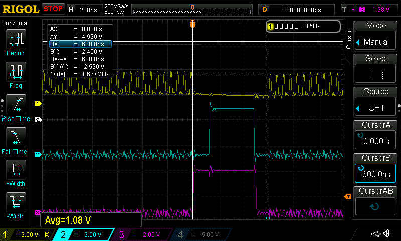
neopixel1.jpg
neopixel1.jpg (66.04 KiB) Viewed 5160 times

The bottom trace there, and what it was triggered on, is the LED pulse line, showing a 500ns T0H pulse.

The middle trace is a GPIO line set high on entry to the timer interrupt routine, and set low on exit from the interrupt. OK, so adding code flip the GPIO will slow it down a bit, but actually, to compensate, I removed the updating of ARR, and also made the resetting of TIM_SR_UIF unconditional. So that indicates it is spending approx 400ns in there, but that does not include interrupt latency...

Finally the top trace show activity in the main while(1) loop, flipping another GPIO there. From that you can see that the mainline code goes out to lunch for just under 600ns when the interrupt occurs.

That was when compiled with GCC, "optimize for speed".

If that is anything to go by, for 400kHz LEDs, you would be using a bit under 24% of the CPU time, and it would be close to 48% for 800kHz LEDs. I'm wondering how this would go on a F103 - I'd guess it could handle 400kHz, but 800kHz could be a challenge.

FWIW it seems to execute around 35 instructions normally. This is up to the point where it is checking lastbit (in original version), which obviously only happens when it runs out of data.

Code: Select all

         TIM4_IRQHandler:
08000cb0:   ldr     r3, [pc, #116]  ; (0x8000d28 <TIM4_IRQHandler+120>)
08000cb2:   ldr     r2, [r3, #16]
08000cb4:   lsls    r2, r2, #31
08000cb6:   bpl.n   0x8000cc0 <TIM4_IRQHandler+16>
109       		TIM4->SR &= ~TIM_SR_UIF; // clear UIF flag
08000cb8:   ldr     r2, [r3, #16]
08000cba:   bic.w   r2, r2, #1
08000cbe:   str     r2, [r3, #16]
112       	if(pos<sizeof(LED_data)){
08000cc0:   ldr     r1, [pc, #104]  ; (0x8000d2c <TIM4_IRQHandler+124>)
08000cc2:   ldrh    r3, [r1, #0]
08000cc4:   cmp     r3, #179        ; 0xb3
08000cc6:   bhi.n   0x8000cf8 <TIM4_IRQHandler+72>
107       void TIM4_IRQHandler(void){
08000cc8:   push    {r4, r5, r6}
113       		if(LED_data[pos] & mask){
08000cca:   ldr     r0, [pc, #100]  ; (0x8000d30 <TIM4_IRQHandler+128>)
08000ccc:   ldr     r4, [pc, #100]  ; (0x8000d34 <TIM4_IRQHandler+132>)
08000cce:   ldrb    r2, [r0, #0]
08000cd0:   ldrb    r4, [r4, r3]
08000cd2:   tst     r2, r4
08000cd4:   bne.n   0x8000d16 <TIM4_IRQHandler+102>
117       			TIM4->CCR1 = low_CCR1;
08000cd6:   ldr     r5, [pc, #96]   ; (0x8000d38 <TIM4_IRQHandler+136>)
08000cd8:   ldr     r4, [pc, #76]   ; (0x8000d28 <TIM4_IRQHandler+120>)
08000cda:   ldrh    r6, [r5, #0]
118       			TIM4->ARR = low_ARR;
08000cdc:   ldr     r5, [pc, #92]   ; (0x8000d3c <TIM4_IRQHandler+140>)
117       			TIM4->CCR1 = low_CCR1;
08000cde:   str     r6, [r4, #52]   ; 0x34
118       			TIM4->ARR = low_ARR;
08000ce0:   ldrh    r5, [r5, #0]
08000ce2:   str     r5, [r4, #44]   ; 0x2c
120       		if(mask==1){
08000ce4:   cmp     r2, #1
121       			mask = 0B10000000;
08000ce6:   itet    eq
08000ce8:   moveq   r2, #128        ; 0x80
123       		}else mask = mask >> 1;
08000cea:   lsrs    r2, r2, #1
122       			pos+=1;
08000cec:   adds    r3, #1
123       		}else mask = mask >> 1;
08000cee:   strb    r2, [r0, #0]
08000cf0:   it      eq
08000cf2:   strheq  r3, [r1, #0]
131       }
08000cf4:   pop     {r4, r5, r6}
08000cf6:   bx      lr
125       		if(lastbit){
08000cf8:   ldr     r3, [pc, #68]   ; (0x8000d40 <TIM4_IRQHandler+144>)
08000cfa:   ldrb    r2, [r3, #0]
08000cfc:   cbz     r2, 0x8000d10 <TIM4_IRQHandler+96>
126       		TIM4->CCER &= ~TIM_CCER_CC1E; //disable output to pin so that it will be low.
ag123
Posts: 1668
Joined: Thu Dec 19, 2019 5:30 am
Answers: 25

Re: [F4] Neopixel driver using hardware timers

Post by ag123 »

flyboy74 wrote: Tue May 05, 2020 11:42 pm
If anyone out there knows assembler I would be interested to know how many machine instructions my interrupter handler uses. I am using a STM32F407 so it is a 32bit RISC running at 168MHz so that is just under 6ns per instruction.
have you tried g++ -S?
that should compile to the assembly listing, i think it is pretty much one instruction per line, so that probably makes counting easier
ozcar
Posts: 144
Joined: Wed Apr 29, 2020 9:07 pm
Answers: 5

Re: [F4] Neopixel driver using hardware timers

Post by ozcar »

flyboy74 wrote: Tue May 05, 2020 11:00 pm ...

Ok I have updated my driver a little to fix this problem Please test it and see if you get good results.

I have changed a few things

1. set the OC1PE as u suggested to ensure CCR and ARR remain in sync.
2. I used to start and stop transmission by enabling or disabling the timer (flick the en bit) now the timer runs the whole time but I set the CCR=0 so that the pin is pulled low and I flick the UIE bit so that the timer doesn't generate a interrupt flag so the interrupt won't fire. Now because the timer is always running just CCR=0 then you don't need to create a preload bit or end of transmission bit.

see https://github.com/OutOfTheBots/STM32_N ... ter/main.c
I grabbed your latest version and tried it out.

The pulse train looked good - no extra long gap at the beginning first time through, and the timings looked spot on.

However...

I wanted to check if the last few pulses were OK, so I butchered the interrupt routine to stop after the first byte. All looked fine, 8 data pulses, and not left floating at the end. I repeated it a couple of times, but the suddenly one time I got only 7 data bits. I repeated it again, and got 8 bits so many times I thought I had been mistaken, but no, I did get only 7 again, after trying maybe twenty times. Long story a tiny bit shorter, it turned out that it was the first data bit that was occasionally going missing.

I made this change and I think it is OK now. I took the liberty of changing the comment there about starting at the second bit (hangover from the previous version) lest the compiler take that as a hint that was what you really wanted to do, given that is exactly what was sometimes happening! Of course, that is not the real reason it was playing up, but I leave you work out exactly what was going on.

Code: Select all

void show_neopixels(){
        pos = 0;                    //set the interupt to start at first byte
	mask = 0B10000000;          //set the interupt to start at first bit
	TIM4->SR &= ~TIM_SR_UIF;    // clear UIF flag
	TIM4->DIER |= TIM_DIER_UIE; //enable interupt flag to be generated to start transmission
}
You could maybe add something to know when the transmission is complete and there was been sufficient delay for the "reset".
Post Reply

Return to “Projects”