emulating a OLED display on a VGA and/or a LCD monitor

Post here all questions related to LibMaple core if you can't find a relevant section!
User avatar
Bakisha
Posts: 140
Joined: Fri Dec 20, 2019 6:50 pm
Answers: 5
Contact:

Re: Looking for a suitable SPI slave example/tutorial

Post by Bakisha »

stevestrong wrote: Thu Dec 17, 2020 11:13 am @Bakisha, that is a perfect example how to use SPI.

1. Instead of using 4 lines to begin the master, you could use only one:
2. You can also send a whole buffer using
1. Yeah, i forgot about that, i was just copy-pasting code from very useful links you previously posted
2. Master code is simplified, so i can send one different byte every 1 milisecond, just to give time to slave to serial print data.
Y@@J wrote: Thu Dec 17, 2020 11:39 am
The data I get are made of bursts of 1048 bytes (=1024 for the pixels + 24 command bytes). I will soon post screen copies of the logic analyzer. Data are very simple, fast (CLK = 1MHz), and frames are separated from each others. 1 second when idle on the info screen, faster when coordinates are to be displayed, or while the user plays with the menus and the encoder.
Well, if you know you have time to process frame after it had been received before data from new frame start coming, then you can use only interrupt at full buffer. I am only worried about sync, is first byte received actually first byte of frame sended?
Regarding VGA, keep in mind it's timing. Every 32uS (i forgot exact number) it will spend in it's interrupt routine around 22uS (not always).
Yes, you might get pixels shifting to the right whenever DMA is blocking CPU cycles or DMA's irq is triggered in the middle of VGA's interrupt.
Just expect that you main program may get interrupt at any point, and your DMA's irq may get delayed around 22uS (as i recall, interrupt cannot interrupt other interrupts in roger's core, but is delayed until previous interrupt is finished).
Y@@J
Posts: 57
Joined: Mon Sep 28, 2020 8:51 pm

Re: Looking for a suitable SPI slave example/tutorial

Post by Y@@J »

Yes I read somewhere IRQs cannot be interrupted.
At this time, I've not tested on VGA, only on terminal. I'm about to start hacking an old VGA cable.

The data, zooming more and more :
PulseView1.JPG
PulseView1.JPG (42.32 KiB) Viewed 4578 times
PulseView2.JPG
PulseView2.JPG (72.82 KiB) Viewed 4578 times
PulseView3.JPG
PulseView3.JPG (54.92 KiB) Viewed 4578 times
Y@@J
Posts: 57
Joined: Mon Sep 28, 2020 8:51 pm

Re: Looking for a suitable SPI slave example/tutorial

Post by Y@@J »

(couldn't post more than 3 files in a post ?)
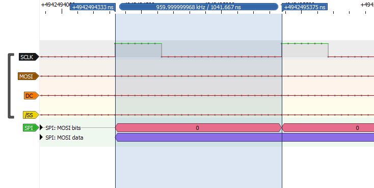
PulseView4.JPG
PulseView4.JPG (39.5 KiB) Viewed 4577 times
As you can see, the data are really simple ! In fact I'm not satisfied. I used a SSD1306 OLED because the protocol is simple. But this display is not supported by Marlin in SPI mode. It has to be done by hand (I posted how to do it on RepRap forum). Wish I could emulate the universal I²C 12864 LCD, as it is always supported. But for now, it is too complicated (and communication with this display is bidirectionnal). Also, I²C could allow for displaying Marlin UI in an Octoprint plugin. Can't believe nobody did it !!!
I²C is the way to go on a RasPi as there's no support for SPI slave mode. Master only.

The code, that works (not sure how and why) ; there was a lot of trial and errors, and I don't understand all the details. Was so focused on, that I just realized stevestrong was on this thread !

As you can see I finally cheat, reading the second page of a 2 page buffer.

Code: Select all

/*
 Name:		SpiSlave32.ino
 Created:	15/12/2020 22:44:11
 Author:	Y@@J and many others...

	SPI SSD1306 emulator

https://web.archive.org/web/20190316162926/https://www.stm32duino.com/viewtopic.php?f=9&t=2846&start=10
https://github.com/rogerclarkmelbourne/Arduino_STM32/pull/503
http://stm32duinoforum.com/forum/viewtopic_f_14_t_3527_start_10.html
https://web.archive.org/web/20190316162929/https://www.stm32duino.com/viewtopic.php?f=9&t=2846
https://web.archive.org/web/20190316155730/https://github.com/stevstrong/Audio-sample/blob/master/stm32/STM32_ADC_Host.ino
https://github.com/stevstrong/Audio-sample/blob/master/stm32/STM32_ADC_Host.ino
https://www.stm32duino.com/viewtopic.php?f=9&t=2846&start=10
https://www.stm32duino.com/viewtopic.php?f=2&t=3

	Hard time to make SPI work in slave mode :
	https://web.archive.org/web/20190316162926/https://www.stm32duino.com/viewtopic.php?f=9&t=2846&start=10
	https://sparklogic.ru/libraries-hardware/hard-time-to-make-spi-work-in-slave-mode.html

	"Without seing your code, i can only suggest to
	- disable DMA,
	- read the SPI data register
	- setup and enable the next DMA transfer.

	The data to be sent must be valid before you do the last step, because the DMA
	will deliver the first byte to transmit to SPI when the SPI is enabled (triggered by the TXE flag)."
	(stevestrong, last post on the thread)

*/

#include <SPI.h>

/*
// CLK : scope -> 1MHz

/!\ PA4 PA5 PA6 PA7 NOT 5V TOLERANT /!\

	pins			STM32				log.analyzer	
#define PIN_SCK		PA5	// SCL				BLACK		SCK
#define PIN_MOSI	PA7	// SDA				BROWN		MOSI
#define PIN_SS		PA4	// AKA CS, A0		YELLOW		Chip Select		LOW on page, HIGH between pages 
#define PIN_MISO	PA6	// 
*/

#define CLK_DIVIDER SPI_CLOCK_DIV16

// Rx buffer
// 8 pages : 8*128 pixels = 8 * 3 bytes (= command) + 8 * 128 bytes (= pixels) = 144

#define FRAME_SIZE		(8 * (3 + 128))
#define BUFFER_SIZE		(2 * FRAME_SIZE)
volatile uint8_t rx_buffer[2*FRAME_SIZE];

// bitmap
volatile uint8_t bitmap[8][128] = { 0 };

// interruption routine
volatile bool dma_transfer_complete = false;
volatile bool dma_transfer_error = false;

void rxDMAirq(void)
{
	//DMA_TRANSFER_COMPLETE,      // Transfer is complete. 
	//DMA_TRANSFER_HALF_COMPLETE, // Transfer is half complete.
	//DMA_TRANSFER_ERROR,         // Error occurred during transfer.
	//DMA_TRANSFER_DME_ERROR,     // Direct mode error occurred during transfer.
	//DMA_TRANSFER_FIFO_ERROR,    // FIFO error occurred during transfer.

	uint32_t dma_isr = dma_get_isr_bits(DMA1, DMA_CH2);

	//if (dma_get_irq_cause(DMA1, DMA_CH2) == DMA_TRANSFER_COMPLETE)
	//{
	//	Serial.println("error : DMA_TRANSFER_COMPLETE");
	//	//dma_transfer_error = true;
	//}

	dma_transfer_complete = true;
}

// decoding ; quickly adapted from the AVR "on the fly" decoding IRQ code
// to be rewritten with page memcpy() 
bool rebuidBitmap()
{
	if (rx_buffer[0] != 0x10 || rx_buffer[1] != 00 || rx_buffer[2] != 0xB0)
		return false;

	for (int i = 0; i < FRAME_SIZE; i++)
		removeCommandBytes(*(rx_buffer + FRAME_SIZE + i));

	return true;
}

void removeCommandBytes(uint8_t dataByte)
{
	static uint8_t* ptr = (uint8_t*)bitmap;
	static unsigned nFrameBytes = 0; // compteur bytes total : 0-1023
	static unsigned nPageBytes = 0; // compteur bytes page : 0-127
	static unsigned nCmdBytes = 0; // compteur bytes cmd début page : 0-2

	// drop 3 bytes
	if (nCmdBytes < 3)
	{
		nCmdBytes++;
		return;
	}

	*(ptr++) = dataByte;
	nFrameBytes++;
	nPageBytes++;

	// 128 bytes = 1 page was read : reset counters
	if (nPageBytes > 127)
		nPageBytes = nCmdBytes = 0;

	if (nFrameBytes > 1023)
	{
		// reset before next call
		ptr = (uint8_t*)bitmap;
		nFrameBytes = nPageBytes = nCmdBytes = 0;
	}
}

// setup functions

void setup()
{
	Serial.begin(250000);
	delay(100);
	setupSPI();
	setupDMA();
}

void setupDMA(void)
{
	dma_init(DMA1);						// SPI is on DMA1
	spi_rx_dma_disable(SPI.dev());		// Disable in case already enabled
	dma_disable(DMA1, DMA_CH2);			// Disable in case it was already enabled
	dma_detach_interrupt(DMA1, DMA_CH2);

	// DMA tube configuration for SPI1 Rx
	dma_tube_config rx_tube_cfg =
	{
		&SPI1->regs->DR,		// Source of data
		DMA_SIZE_8BITS,			// Source transfer size
		&rx_buffer,				// Destination of data
		DMA_SIZE_8BITS,			// Destination transfer size
		BUFFER_SIZE,			// Number of data to transfer
								// Flags :
		DMA_CFG_DST_INC |		// auto increment destination address
		DMA_CFG_CIRC	|		// circular buffer
		DMA_CFG_CMPLT_IE |		// set tube full IRQ
		DMA_CCR_PL_VERY_HIGH,	// very high priority
		0,						// Un-used
		DMA_REQ_SRC_SPI1_RX		// Hardware DMA request source
	};

	// SPI1 Rx is channel 2
	int ret_rx = dma_tube_cfg(DMA1, DMA_CH2, &rx_tube_cfg);
	
	if (ret_rx != DMA_TUBE_CFG_SUCCESS)
	{
		while (1)
		{
			Serial.print("Rx DMA configuration error: ");
			Serial.println(ret_rx, HEX);
			Serial.println("Reset is needed!");
			delay(100);
		}
	}

	spi_rx_reg(SPI.dev());							// Clear RX register in case we already received SPI data
	dma_attach_interrupt(DMA1, DMA_CH2, rxDMAirq);	// Attach interrupt to catch end of DMA transfer
	dma_enable(DMA1, DMA_CH2);						// Rx : Enable DMA configurations
	spi_rx_dma_enable(SPI.dev());					// Tx : SPI DMA requests for Rx and Tx 
}

void setupSPI(void)
{
	// MOSI, MISO, SCK PINs are set by the library
	pinMode(BOARD_SPI_DEFAULT_SS, INPUT); // SS
	
	///// ?????
	SPI.setModule(1);

	// "The clock value is not used, SPI1 is selected by default"  ?????????????
	// 
	//SPISettings spiSettings(CLK_DIVIDER, MSBFIRST, SPI_MODE0, DATA_SIZE_8BIT);
	SPISettings spiSettings(0, MSBFIRST, SPI_MODE0, DATA_SIZE_8BIT);

	SPI.beginTransactionSlave(spiSettings);

	// Clear RX register in case we already received SPI data
	spi_rx_reg(SPI.dev()); // ???
}

// loop() and display

void loop()
{
	if (dma_transfer_complete)
	{
		if (rebuidBitmap())
			printFrame();

		dma_transfer_complete = false;
	}

	delay(500);
}

void printFrame()
{
	for (int page = 0; page < 8; page++)
	{
		// 128 blocs de 8 lignes ; bits de poids faible = ligne du haut
		for (int line = 0; line < 8; line++)
		{
			for (int col = 0; col < 128; col++)
			{
				uint8_t val = bitmap[page][col];
				if (val & (1 << line))
					Serial.print('#');
				else
					Serial.print(' ');
			}

			Serial.println();
		}
	}
	for (int i = 0; i < 128; i++)
		Serial.print('X');

	Serial.println();
}
User avatar
Bakisha
Posts: 140
Joined: Fri Dec 20, 2019 6:50 pm
Answers: 5
Contact:

Re: Looking for a suitable SPI slave example/tutorial

Post by Bakisha »

Looks OK to me. Maybe remove delay from main loop?
Basically,

Code: Select all

if (rebuidBitmap())
printFrame();
must end before /SS line goes LOW again.

Only error i could think of is that slave must be ready to receive data on power up before master start to send any data, or you might get your data shifted.
As, instead:
rx_buffer[0] = 0x10 , rx_buffer[1] = 00 , rx_buffer[2] = 0xB0
you might end with
rx_buffer[0] = 00 , rx_buffer[1] = 0xB0 , rx_buffer[1047] = 0x10 (or rx_buffer[2095] = 0x10 if you are using double size buffer)
feluga
Posts: 64
Joined: Wed Mar 18, 2020 2:50 am

Re: Looking for a suitable SPI slave example/tutorial

Post by feluga »

Y@@J wrote: Thu Dec 17, 2020 2:32 pm Yes I read somewhere IRQs cannot be interrupted.
IRQ can be interrupted, always when you know what you are doing...
In order to allow one IRQ to interrupt another, it's necessary to set Interrupt Priority on NVIC, using CMSIS, NVIC_SetPriority().
The lower the priority number, the higher will be its priority.

More information at:
http://www.disca.upv.es/aperles/arm_cor ... c__gr.html
https://www.keil.com/pack/doc/CMSIS/Cor ... CMSIS.html
Y@@J
Posts: 57
Joined: Mon Sep 28, 2020 8:51 pm

Re: Looking for a suitable SPI slave example/tutorial

Post by Y@@J »

@ Bakisha : In order to speed the thing up, if I could use the DC signal... DC is LOW when the command bytes are sent. If I could tell SPI not to take these bytes while DC is down, I could maybe write "directly" to the video buffer. Would still require bit masking/reading and writing bytes. Still searching about video drivers : ideally, it would be monochrome, with 1bit/pixel.

I have the BlueVGA demo running, and new problem : it runs (with some glitches) on an old LCD monitor, but not on the 52Pi LCD (https://wiki.52pi.com/index.php/7-Inch- ... U:_EP-0084) : it cannot "read" the signal. With TVOut (composite), the demo worked with NTSC only. And no knowledge about TV/Video ! Maybe have to make a VGA to composite adapter, and see what happens.

Will see for power up chronology when I get a VGA display : can't test at the moment, and have to learn BlueVGA (or other lib)

@feluga : this is well beyond what I'm able to do !!! But I see the thing. Reminds the BIOS interrupt tables and hardware interrupts and their priorities (had to deal with 30 years ago).
User avatar
Bakisha
Posts: 140
Joined: Fri Dec 20, 2019 6:50 pm
Answers: 5
Contact:

Re: Looking for a suitable SPI slave example/tutorial

Post by Bakisha »

Without external electronic, i don't know how to combine DS and /SS signal when receiving SPI.
I would use more blunt solution:
-copy rx_buffer to 2nd_rx_buffer as soon as dma_transfer_complete = true
-search in 2nd_rx_buffer sequence of 0x10 , 0x00 , 0xB0
-once found set it as offset
-copy from 2nd_rx_buffer from offset to end of buffer to 3rd_rx_buffer from position 0
-copy from 2nd_rx_buffer from position 0 to offset to 3rd_rx_buffer from position (1048 - offset)

But that is just idea. I recommend you test code you made so far, and if it's working, no need to over-complicate things.

As for VGA, i also had problems. And i never figure out what is causing it. Maybe it was my crappy dupont wires on breadboard, maybe it's up to monitor what kind of signal it's expecting, maybe it bad sourcing/sinking capabilities of PORTC pins on bluepill's clones.
Try grounding blue/red pins on vga side and use only green from bluepill, or put 330 Ohm resistors in series with R/G/B. Maybe even on HSYNC/VSYNC pins.

VGA and TV signals are deep rabbit hole, once i tried and even i got steady picture, but i never finished that project...
Y@@J
Posts: 57
Joined: Mon Sep 28, 2020 8:51 pm

Re: Looking for a suitable SPI slave example/tutorial

Post by Y@@J »

"Without external electronic..."

And why not with ? And why didn't I think of this before you suggest it ? Output /SS LOW when input /SS is LOW and DC is HIGH ; should be doable with a couple of NAND gates. (not used to logical circuits, didn't draw the truth table). And no such ICs here, will have to order. Or use some tranies...

I added the 330R resistors : no difference (no image).
https://github.com/mubes/vidout : "Note that the spec calls for VSYNC/HSYNC to be 5V and Video to be 1V max"
Will have to try pumping up the SYNC signals... (at the moment 330R on all 5 lines) Didn't know about 5V :

I was also surprised PC13/14/15 were used. (but it's a good idea as they are often the last ones on a project).
Also tried mixing VSYNC HSYNC and a color : nothing (found this weird trick on the web, could be an april's fool).
And some tricks on BlueVGA Git about timings : https://github.com/RoCorbera/BlueVGA/issues/4 (exactly my issue on the monitor, looks like jitter)
The LCD is driven by a PCB800099 module, with a Realtek RTD2660 onboard, but supported resolutions for this one LCD are not specified. Lots of hacked firmwares, but for salvaged laptop LCDs. Will see if Pixel can be set at HDMI 640x480 on a RasPi (assuming analog HDMI), and plug the LCD. It allows 128x64 for sure, but NTSC only.
Also searched for a BluePill->composite lib : nothing usable :
There's also Artekit (green on black is just perfect). But for the other core, don't know if it could run with Roger's one.
User avatar
Bakisha
Posts: 140
Joined: Fri Dec 20, 2019 6:50 pm
Answers: 5
Contact:

Re: Looking for a suitable SPI slave example/tutorial

Post by Bakisha »

Artekit used DMA stream to SPI, so i don't think it's usefull in your project.

Another idea is simpler one:
Example sketch from roger core, https://github.com/rogerclarkmelbourne/ ... udeVGA.ino

But instead of bit-banged colors, you can use SPI2 port to send pixel data.
In isr_start it could be something like:

Code: Select all

for (i=0;i<16;i++) {// 16*8=128 pixels
SPI2->regs->DR = (byte_to_send) ; 
...calculate next byte
while (SPI2->regs->SR & (!SPI_SR_TXE)) {}; // wait until send buffer is cleared
} // i
SPI2->regs->DR = (0) ; // last bit must be 0, or MOSi will stay HIGH
If SPI2 is set to 9MHz, 16 bytes should be 14.22uS long in total when sending. If my calculations are correct, while SPI2 is sending byte (0.88uS) there is enough time CPU can calculate next byte.

If you get unstable picture, disable systick with

Code: Select all

systick_disable();
Y@@J
Posts: 57
Joined: Mon Sep 28, 2020 8:51 pm

Re: Looking for a suitable SPI slave example/tutorial

Post by Y@@J »

Found an old WinXP laptop, with VGA connector (completely forgot about it...). Bad news : DDC information for VGA : 1024x600 and 800x600. No 640x480, dead end. CrudeVGA can do nothing.

An idea : the BluePill behaving as a 128x64 px(or multiple) 2bit USB cam (could be displayed in the OctoPrint webcam tab or better in a plugin to be written) ; found this : https://github.com/duvitech/ST-NUCLEO-F429ZI-CAM ; declares itself as a USB Video Class device. (in fact Marlin in OctoPrint was my first dream, and would be a good entry point for Python and plugin coding)

[EDIT] or configuring the 2nd SPI (or I²C) port as slave, sending data to the RasPi being the master... The goal is to display images on the LCD, the way it receives them does not matter. And 4 cores 1GHz + GPU instead of one and 72MHz ; + some learning. 1st step could be displaying the "ascii art Marlin" in a Linux terminal. Currently flashing a Pi. When done, will began with answering commands and sending data over the 2nd SPI port. How to make a RasPi a SPI slave ? Just hook a BluePill SPI slave. Should work. Marlin -> OLED data -> SPI -> STM32 -> SPI -> RasPi -> 7" LCD
Post Reply

Return to “General discussion”