
Hi,
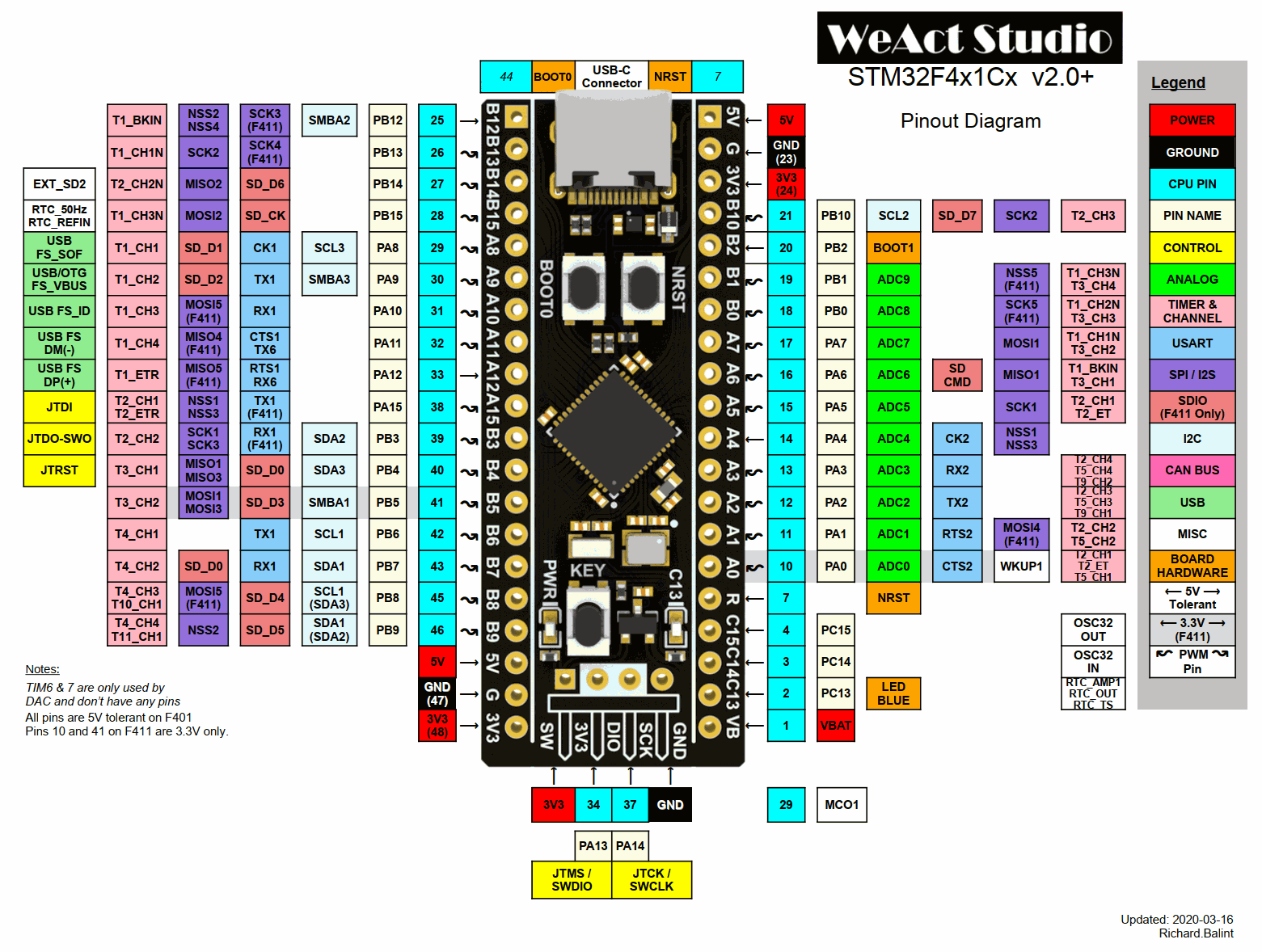
Could someone explain me why on earth on the board diagram of the blackpill there are three USART1 ports (rx1 on pins PA10,PB3,PB7 ant tx1 on pins PA9,PA15,PB6). I was able to run USART1 on PB6 and PB7, USART2 on PA3 and PA2 and the USB-C is on the PA11 and PA12. Are the other USART1 pins some how usable as separate rx-tx ports. If Yes than How? If not then why they are there. Usually if some pins are multi usage (like USART and I2C etc) then they are usable but in this case I was not able to get the other USART1 to run.
Thanks
USART on STM32F411 BlackPill
Re: USART on STM32F411 BlackPill
Those are alternate pins.
PA9 and PA10 are used with USB,
PB6 and PB7 are used with I2C1
so if you cannot use them you have 3rd pair: PA15 and PB3 but you need to change pin assignment:
https://github.com/stm32duino/wiki/wiki ... wareserial
PA9 and PA10 are used with USB,
PB6 and PB7 are used with I2C1
so if you cannot use them you have 3rd pair: PA15 and PB3 but you need to change pin assignment:
https://github.com/stm32duino/wiki/wiki ... wareserial
-
stevestrong
- Posts: 505
- Joined: Fri Dec 27, 2019 4:53 pm
- Location: Munich, Germany
- Contact:
Re: USART on STM32F411 BlackPill
Which block diagram do you refer to?
How did you manage to use USART1 on PB6/7?
Please always post links/code, otherwise we cannot read your thoughts.
PA9/10 are usually TX1, RX1.
PA11/12 are USB pins.
How did you manage to use USART1 on PB6/7?
Please always post links/code, otherwise we cannot read your thoughts.
PA9/10 are usually TX1, RX1.
PA11/12 are USB pins.
Last edited by stevestrong on Fri Apr 02, 2021 3:52 pm, edited 1 time in total.
Re: USART on STM32F411 BlackPill
Thanks GonzoG for the link. I omitted this info somehow ... But thanks to this I was able to redirect USART1 to different pins. At the begining I was doing this wrong.
SteveStrong You are right, thanks for the correction. I've made a mistake in first post putting wrong pin names.
Now HW Serial is working as in here:
I was referring to this diagram
https://miro.medium.com/max/3122/1*ixFS ... 0w6jFA.png
Unfortunately I'm still having problems with getting the SoftwareSerial running. It is also in the code above and it is not sending any data. Someone else has similar problem so I wrote also in other thread but still nothing. Can You guys help me with this also?
SteveStrong You are right, thanks for the correction. I've made a mistake in first post putting wrong pin names.
Now HW Serial is working as in here:
Code: Select all
HardwareSerial Serial2(USART2);

#include <SoftwareSerial.h>

SoftwareSerial mySerial(PB1, PB0); // RX, TX

void setup() {
  Serial1.setRx(PB7);
  Serial1.setTx(PB6);
  Serial1.begin(115200);
  Serial2.begin(115200);
  mySerial.begin(9600);


}

void loop() {
  Serial1.println("hello 1");
  Serial2.println("hello 2");
  mySerial.println("hello 3");
  delay(1000);
}
https://miro.medium.com/max/3122/1*ixFS ... 0w6jFA.png
Unfortunately I'm still having problems with getting the SoftwareSerial running. It is also in the code above and it is not sending any data. Someone else has similar problem so I wrote also in other thread but still nothing. Can You guys help me with this also?
-
elliotP890
- Posts: 1
- Joined: Fri Apr 02, 2021 12:01 pm
Re: USART on STM32F411 BlackPill
Hey guys,
I'm in the same position as the original post, and I'm having difficulty understanding the replying posts. I need to use 2 serial ports for a drone project on my STM32F411 board. One is for my reciever (just an Rx pin), and one for a GPS module. Using the same pinout diagram that's been posted here already: https://miro.medium.com/max/3122/1*ixFS ... 0w6jFA.png
I don't understand why there are multiple serial1 ports and if its possible to use 2 different serial ports. I'm also using the usb occasionally to use the serial monitor in Arduino. Are the multiple serial1 ports simply just different pins to redirect USART1 or can I using them as separate serial connections?
Also why is there Tx6 and Rx6 (A11 and A12) on the board? Really struggling to understand this, my understanding was that different serial ports were labelled Tx/Rx and numbered accordingly. Can someone help me understand this?
Thanks,
Elliot
Re: USART on STM32F411 BlackPill
normally uart1 is on pa9, pa10
uart2 is on pa2, pa3
other things are check in the core files if they are declared that way, or if you are declaring it manually you may need to specify the pns
https://github.com/stm32duino/wiki/wiki ... wareserial
then some functions can be remapped to other pins, but if you are able to use the default pins above, they could be 'easier'
Re: USART on STM32F411 BlackPill
Hi guys,
For the past few days, I've tried to make my STM32F11CE BlackPill Work Properly with PlatformIO. While the original post is not about PlatformIO, this is one of the few threads that I have found useful in my journey. I finally managed to get it working the way I wanted to: using the USB connector to talk to my PC.
Apparently there's a problem in PIO's build scripts: https://community.platformio.org/t/diff ... ng/7501/18
Basically adding the following will probably solve the problem:
Also note that (at least in my case) the USB communication only works if I use the standard "Serial" definition in my code, as in Serial.begin(115200);
Using Serial1 does not appear to work, even tough "Serial" appears to be defined as "Serial1" in WSerial.h at line 58:
My guess is that using "monitor_dtr = 1" defines Serial somewhere else.
For the past few days, I've tried to make my STM32F11CE BlackPill Work Properly with PlatformIO. While the original post is not about PlatformIO, this is one of the few threads that I have found useful in my journey. I finally managed to get it working the way I wanted to: using the USB connector to talk to my PC.
Apparently there's a problem in PIO's build scripts: https://community.platformio.org/t/diff ... ng/7501/18
Basically adding the following will probably solve the problem:
Code: Select all
build_flags =
    -D PIO_FRAMEWORK_ARDUINO_ENABLE_CDC
    -D USBCON

monitor_dtr = 1Using Serial1 does not appear to work, even tough "Serial" appears to be defined as "Serial1" in WSerial.h at line 58:
Code: Select all
#if !defined(Serial)
        #define Serial Serial1
        #define serialEvent serialEvent1
#endifRe: USART on STM32F411 BlackPill
Serialx (Serial1, Serial2, etc) is for U(S)ART only.Olareanu wrote: Tue Feb 08, 2022 4:12 pm Also note that (at least in my case) the USB communication only works if I use the standard "Serial" definition in my code, as in Serial.begin(115200);
Using Serial1 does not appear to work, even tough "Serial" appears to be defined as "Serial1" in WSerial.h at line 58:
My guess is that using "monitor_dtr = 1" defines Serial somewhere else.Code: Select all
#if !defined(Serial)
        #define Serial Serial1
        #define serialEvent serialEvent1
 #endif
And the code you quoted means that if there is no "Serial" defined, define "Serial" as "Serial1". It will then replace every occurrence of "Serial" with "Serial1".
Re: USART on STM32F411 BlackPill
Code: Select all
    -D PIO_FRAMEWORK_ARDUINO_ENABLE_CDC
-D USBCONRe: USART on STM32F411 BlackPill
I still have some unanswered questions about this thing, you guys might be able to help me out:
Can you start HardwareSerial on any pins you like? Certaintly seems like it here: https://github.com/stm32duino/wiki/wiki ... -functions
I haven't got it to work tough. It works if I create the HardwareSerial Objects on the pins from the pinout diagram like so:
but bot if I change it up like so:
The code compiles, but nothing appears to be sent or recieved. This is the rest of the code I used to test this:
And here's my .ini file, as I'm using PlatformIO:
Somewhat unrelated: On the chip manufacturer's website (https://www.st.com/en/microcontrollers- ... 2f411.html), it says that the stm32f411 supports 3 USARTs and an USB 2.0 OTG. Does that mean you can start 3 diffrent Serial connections and the USB at once or is one of the USARTs taken up by the USB?
Can you start HardwareSerial on any pins you like? Certaintly seems like it here: https://github.com/stm32duino/wiki/wiki ... -functions
I haven't got it to work tough. It works if I create the HardwareSerial Objects on the pins from the pinout diagram like so:
Code: Select all
HardwareSerial FirstSerial(PA10, PA9);
HardwareSerial SecondSerial(PA3, PA2);Code: Select all
HardwareSerial FirstSerial(PA10, PA8);
HardwareSerial SecondSerial(PA3, PA2);Code: Select all
#include <Arduino.h>

HardwareSerial FirstSerial(PA10, PA9);
HardwareSerial SecondSerial(PA3, PA2);

//HardwareSerial FirstSerial(PA10, PA8);
//HardwareSerial SecondSerial(PA3, PA2);

void setup() {
    Serial.begin(115200);
    while(!Serial);

//    FirstSerial.setTx(PA8);           - This didn't work
    delay(100);

    FirstSerial.begin(115200);
    SecondSerial.begin(115200);
    pinMode(PC13, OUTPUT);
    digitalWrite(PC13,LOW);
}

void loop(){
    for (int i = 1; i <= 32; ++i) {


        byte incomingByte{};
        byte sentByte{};

        FirstSerial.write(i);
        delay(10);
        if (SecondSerial.available()) {
            incomingByte = SecondSerial.read();
        }

        SecondSerial.write(incomingByte);
        delay(10);
        if (FirstSerial.available()) {
            sentByte = FirstSerial.read();
        }

        if ((incomingByte == sentByte) && (incomingByte != 0)) {
            Serial.print("Test ok, received: ");
            Serial.print(incomingByte);
            Serial.print(" , ");
            Serial.println(sentByte);
        } else {
            Serial.print("Test NOT ok, received: ");
            Serial.print(incomingByte);
            Serial.print(" , ");
            Serial.println(sentByte);
        }

        delay(500);
    }
}
And here's my .ini file, as I'm using PlatformIO:
Code: Select all
; PlatformIO Project Configuration File
;
;   Build options: build flags, source filter
;   Upload options: custom upload port, speed and extra flags
;   Library options: dependencies, extra library storages
;   Advanced options: extra scripting
;
; Please visit documentation for the other options and examples
; https://docs.platformio.org/page/projectconf.html

[env:blackpill_f411ce]
platform = ststm32
board = blackpill_f411ce
framework = arduino

monitor_speed = 115200
upload_protocol = dfu

build_flags =
    -D PIO_FRAMEWORK_ARDUINO_ENABLE_CDC
    -D USBCON

monitor_dtr = 1
Somewhat unrelated: On the chip manufacturer's website (https://www.st.com/en/microcontrollers- ... 2f411.html), it says that the stm32f411 supports 3 USARTs and an USB 2.0 OTG. Does that mean you can start 3 diffrent Serial connections and the USB at once or is one of the USARTs taken up by the USB?