STM32 GPSDO

What are you developing?
AndrewBCN
Posts: 105
Joined: Sun Apr 25, 2021 3:50 pm
Answers: 1
Location: Strasbourg, France

STM32 GPSDO

Post by AndrewBCN »

I am working on an STM32 GPSDO. Or perhaps I should describe my project as "Yet another GPSDO, but this one uses an STM32 MCU" since there are so many GPSDO projects available on the internet. But I believe my project is the first one based on an STM32 MCU.

What is a GPSDO? A GPSDO is a GPS-disciplined oscillator, meaning it's an oscillator that has its frequency stabilized by a GPS signal. Usually, the oscillator is an OCXO* (oven controlled crystal oscillator), but it could be a TCXO (temperature controlled crystal oscillator) or even a rubidium oscillator.

In my project I am using a recycled 10 MHz, 5V, square wave OCXO, available on the internet for less than €10, a WeAct STM32F411CEU6 "Black Pill" development board, and a u-blox NEO-M8 GPS receiver module. Power is entirely provided by the USB C connector on the Black Pill, power consumption is 4W during OCXO warming and decreases to <2W in steady state operation.

A small OLED connected to the I2C bus provides some information, and I am thinking of adding a Bluetooth module to allow wireless connection to a smartphone or PC.

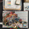
I am developing the firmware using Arduino IDE 1.8.13 with STM32 Core release 2.0.0. Flashing the firmware is done using the DFU method. The hardware prototype is implemented on a pair of breadboards, and the wiring is a mess! But hey, it works... :D

Image

*: If anybody is interested in the subject, a good starting point for further reading is the Wikipedia page on OCXO's :arrow: : https://en.wikipedia.org/wiki/Crystal_oven
Last edited by AndrewBCN on Sun May 02, 2021 6:52 pm, edited 1 time in total.
User avatar
fpiSTM
Posts: 1738
Joined: Wed Dec 11, 2019 7:11 pm
Answers: 91
Location: Le Mans
Contact:

Re: STM32 GPSDO

Post by fpiSTM »

Nice project. Thanks for sharing.
AndrewBCN
Posts: 105
Joined: Sun Apr 25, 2021 3:50 pm
Answers: 1
Location: Strasbourg, France

Re: STM32 GPSDO

Post by AndrewBCN »

fpiSTM wrote: Wed Apr 28, 2021 11:57 am Nice project. Thanks for sharing.
Thank you, and thank you for your help here and on GitHub. I will post more details as I advance through the project, and I intend to post the firmware source code on GitHub once it stabilizes a bit (I got the frequency measurement algorithm working this morning for the first time :) ). I am really enjoying development on the STM32F411CEU6, it's an incredibly powerful MCU, and this project is giving me the opportunity to explore various buses and peripherals that the STM32 MCU supports (I2C, SPI, serial, the flexible timers, the ADC, interrupts, etc).
mlundin
Posts: 94
Joined: Wed Nov 04, 2020 1:20 pm
Answers: 6
Location: Sweden

Re: STM32 GPSDO

Post by mlundin »

I am playing with similar ideas, but I am using the Nucleo L432 board. Nice thing is that there is no onboard high frequency crystal so the OSC input is exposed and ready to use. This makes it possible to drive the MCU with the output from the disciplined osc, simplifying the timing.
AndrewBCN
Posts: 105
Joined: Sun Apr 25, 2021 3:50 pm
Answers: 1
Location: Strasbourg, France

Re: STM32 GPSDO

Post by AndrewBCN »

mlundin wrote: Thu Apr 29, 2021 6:36 am I am playing with similar ideas, but I am using the Nucleo L432 board. Nice thing is that there is no onboard high frequency crystal so the OSC input is exposed and ready to use. This makes it possible to drive the MCU with the output from the disciplined osc, simplifying the timing.
Indeed the Nucleo L432 is an excellent choice for this application. The disadvantage I see to using the output from the disciplined oscillator to drive the MCU PLL is that you'll have to program the PLL yourself.
In the case of the STM32F411CEU6 Black Pill which I am using, there is an onboard 25MHz crystal driving the HSE, and the OSC input is not exposed. I have connected the output from the disciplined oscillator (the OCXO) to the ETR input of 32-bit timer 2 to measure its frequency (the 1PPS output from the GPS is connected to timer 2 channel 3 in input capture mode). You can use exactly the same setup on the Nucleo L432 board since the timer 2 is identical for both MCU's. And you have the advantage that you can use the internal DAC to "close the control loop", whereas I had to use an external I2C DAC.
mlundin
Posts: 94
Joined: Wed Nov 04, 2020 1:20 pm
Answers: 6
Location: Sweden

Re: STM32 GPSDO

Post by mlundin »

Setting up the clock for 10MHz external osc and 80 MHz working frequency is simple

Code: Select all

/* Configure 10MHz external TCO as system clock source 
*  Make sure to #define  HSE_VALUE  10000000
*/
void InitHSE() {
  RCC_OscInitTypeDef RCC_OscInitStruct = {};
  RCC_ClkInitTypeDef RCC_ClkInitStruct = {};

  /* Reset to MSI and no PLL */ 
  RCC_ClkInitStruct.ClockType = RCC_CLOCKTYPE_HCLK | RCC_CLOCKTYPE_SYSCLK
                                | RCC_CLOCKTYPE_PCLK1 | RCC_CLOCKTYPE_PCLK2;
  RCC_ClkInitStruct.SYSCLKSource = 0 /*RCC_SYSCLKSOURCE_MSICLK*/;
  RCC_ClkInitStruct.AHBCLKDivider = RCC_SYSCLK_DIV1;
  RCC_ClkInitStruct.APB1CLKDivider = RCC_HCLK_DIV1;
  RCC_ClkInitStruct.APB2CLKDivider = RCC_HCLK_DIV1;

  HAL_RCC_ClockConfig(&RCC_ClkInitStruct, FLASH_LATENCY_4);

  /* Enable HSE externalOscillator with bypass and activate PLL with HSE as source */
  /* 10MHz * 16 / 2 = 80MHz */
  RCC_OscInitStruct.OscillatorType = RCC_OSCILLATORTYPE_HSE;
  RCC_OscInitStruct.HSEState = RCC_HSE_BYPASS;
  RCC_OscInitStruct.PLL.PLLState = RCC_PLL_ON;
  RCC_OscInitStruct.PLL.PLLSource = RCC_PLLSOURCE_HSE;
  RCC_OscInitStruct.PLL.PLLM = 1;
  RCC_OscInitStruct.PLL.PLLN = 16;
  RCC_OscInitStruct.PLL.PLLR = 2;
  RCC_OscInitStruct.PLL.PLLP = 7;
  RCC_OscInitStruct.PLL.PLLQ = 4;
  HAL_RCC_OscConfig(&RCC_OscInitStruct);  

  RCC_ClkInitStruct.ClockType = RCC_CLOCKTYPE_HCLK | RCC_CLOCKTYPE_SYSCLK
                                | RCC_CLOCKTYPE_PCLK1 | RCC_CLOCKTYPE_PCLK2;
  RCC_ClkInitStruct.SYSCLKSource = RCC_SYSCLKSOURCE_PLLCLK;
  RCC_ClkInitStruct.AHBCLKDivider = RCC_SYSCLK_DIV1;
  RCC_ClkInitStruct.APB1CLKDivider = RCC_HCLK_DIV1;
  RCC_ClkInitStruct.APB2CLKDivider = RCC_HCLK_DIV1;

  HAL_RCC_ClockConfig(&RCC_ClkInitStruct, FLASH_LATENCY_4);

}
Then we define the HSE value in hal_conf_extra.h as #define HSE_VALUE 10000000
AndrewBCN
Posts: 105
Joined: Sun Apr 25, 2021 3:50 pm
Answers: 1
Location: Strasbourg, France

Re: STM32 GPSDO

Post by AndrewBCN »

Right now I have the frequency measurement algorithm working, the GPS handled using the TinyGPSplus library, various sensors connected, the OLED display is showing some useful information, and USB CDC serial is providing a ton of data.

I wrote the code for the ring buffers that allows measuring the OCXO frequency to 0.1Hz, 0.01Hz and 0.001Hz resolution, and the code works, but measurements to 0.001Hz (using a 1000s ring buffer) are in my opinion just useless. A 0.01Hz accuracy already represents 1 ppb (10^⁻9) for a 10MHz oscillator, and that's more than good enough for any home lab application.

Here is a sample of the USB serial information sent around 6 times per second to the laptop which also powers the GPSDO:

Code: Select all

VRef(mv)= 3313	Temp(°C)= 28	Vbat(mv)= 810	A0(mv)= 922
Temperature: 18.68 degrees C
Humidity: 61.25% rH
Location: 48.560777,7.781776  Date/Time: 5/2/2021 15:01:46
Counter: 2007356364 Frequency: 10000000 Hz
10s Frequency Avg: 10000000.0 Hz
100s Frequency Avg: 10000000.01 Hz
Vctl: 2.15
Temperature = 17.98 *C
Pressure = 1004.03 hPa
Approx altitude = 124.67 m
These are, in order:
1. STM32F411CEU6 internal sensors. A0 is actually connected to the user button and reads 0~3mV when the button is pressed.
2, 3. Temperature and humidity data from AHT10 sensor.
4. GPS data. Also available but not shown: the number of satellites tracked.
5. CCR3 reading for that second, and the calculated frequency.
6. 10s frequency average.
7. 100s frequency average.
8. Voltage applied to the control input of the OCXO.
9, 10, 11. Temperature, atmospheric pressure and calculated altitude from BMP280 sensor.

On my todo list for the coming weeks: a self-calibration algorithm (that is required because different OCXO's have different characteristics), bluetooth connection to a smartphone/PC, and of course, documentation.
dannyf
Posts: 447
Joined: Sat Jul 04, 2020 7:46 pm

Re: STM32 GPSDO

Post by dannyf »

I did a similar project with a pic(16f1936), with little external parts. Essentially you use the pps signal from the GPS to gate pulse counting against a vcxo. The voltage to the vcxo is based on the counting and an algorithm. No need for temp or humidity sensor.
AndrewBCN
Posts: 105
Joined: Sun Apr 25, 2021 3:50 pm
Answers: 1
Location: Strasbourg, France

Re: STM32 GPSDO

Post by AndrewBCN »

dannyf wrote: Thu May 06, 2021 1:49 am I did a similar project with a pic(16f1936), with little external parts. Essentially you use the pps signal from the GPS to gate pulse counting against a vcxo. The voltage to the vcxo is based on the counting and an algorithm. No need for temp or humidity sensor.
Hi Danny,
Indeed, the USB serial interface to a PC, the bluetooth interface (which I just got working today), the various sensors and the small OLED display, all this is optional if all you want is a "black box" GPS-disciplined 10MHz signal generator with decent stability.
But that's exactly the point of this STM32 project vs all the other GPSDO projects (at least a dozen) described on the web, which are generally based on an Arduino or a PIC: the STM32 MCU has many more interfaces, more ram and flash, runs much faster (100MHz) and allows for much more sophisticated control algorithms. And the programming environment, library availability and ease of testing with the Arduino IDE make code development and debugging a breeze.
When I compare that to many other GPSDO projects that use AVR or PIC assembly language resulting in a firmware that is essentially unmaintainable, I feel that the really inexpensive (5€) STM32 development board that I decided to use was by far the best choice.
To give you an idea: the frequency measurement timer setup routine - the core routine in this project - that I wrote requires just 6 lines of fairly easy to understand C code, no interrupts and no DMA. That would be completely impossible to achieve in assembly language.
I feel that for a lesser amount of programming, I can have a much more interesting project with sophisticated environmental monitoring, a rich user interface and unlimited choices when it comes to the frequency locked loop control algorithm.
BTW: I have been reading your posts on STM32 timer programming in your blog with much interest and I wanted to thank you for sharing your code and knowledge.
https://dannyelectronics.wordpress.com/ ... it-timers/
AndrewBCN
Posts: 105
Joined: Sun Apr 25, 2021 3:50 pm
Answers: 1
Location: Strasbourg, France

STM32 GPSDO: first milestone achieved

Post by AndrewBCN »

This STM32 GPSDO project has reached its first milestone today: the frequency locked loop has been "closed" in software and achieves 10^-9 (10MHz +/- 0.01Hz) stability - as far as I can tell, since I obviously don't have an even better clock to compare against.

Here is the output the little STM32F411CEU6 development board spits out on the Arduino monitor through the USB CDC serial connection, multiple times per second:

Code: Select all

VRef(mv)= 3313	Temp(°C)= 29	Vbat(mv)= 810	A0(mv)= 812
Temperature: 19.43 degrees C
Humidity: 63.55% rH
Location: 48.560770,7.781797  Date/Time: 5/6/2021 17:08:12
Counter: 2554081315 Frequency: 10000000 Hz
10s Frequency Avg: 10000000.0 Hz
100s Frequency Avg: 9999999.99 Hz
Vctl: 2.15
Temperature = 18.89 *C
Pressure = 989.62 hPa
Approx altitude = 246.12 m
The control loop adjusts the OCXO control voltage by around 3.3V/4096 up or down around an initial value set at 2.10V, once every 400 seconds when the GPS is locked; yes, I know that's an extremely crude algorithm, but I'll get around to implementing a proper PID algorithm sometime later. Also I have yet to think about, draft, and then implement a proper algorithm for holdover mode (when the GPS module cannot achieve a "lock" on a sufficient number of satellites and thus does not provide a 1PPS signal). And a self-calibration routine. Etc.
Well, one step at a time. This is already by far the most precise clock I have ever built: 10^-9 means this GPSDO will lose/gain less than 1 second every 30 years. That's certainly good enough for my modest home lab!
Post Reply

Return to “Projects”