Another thing I'd likely try is to place an
RC low pass filter before the ADC input or before an Op-Amp as a buffer.
I managed to make a bode plot for an RC filter

- bode plot
- rc1.png (11.02 KiB) Viewed 22859 times
This is for
R = 500 ohms
C = 1.0uF
It gives me a -3 dB cut-off frequency of 318.3 Hz.
The data sheet for
LMT86, stated that for 1 uF, the minimum R value needs to be 1 K ohm.
I'm not sure if that is a strict limit or that it is merely a suggestion. The trouble is, if 1 K ohm is used, the cut-off frequency falls to 159.15 Hz.
While a low cut-off value is good, the phase lag can be quite extreme. During rapid heating, say when I replace it with a thermistor eventually, actual hot end temperatures may exceed the filtered value and may be quite a bit higher than the value at the ADC. This may cause some troubles for PID controls, I'd guess.
I took a look at the impulse step response using R = 1K and C = 1 uF
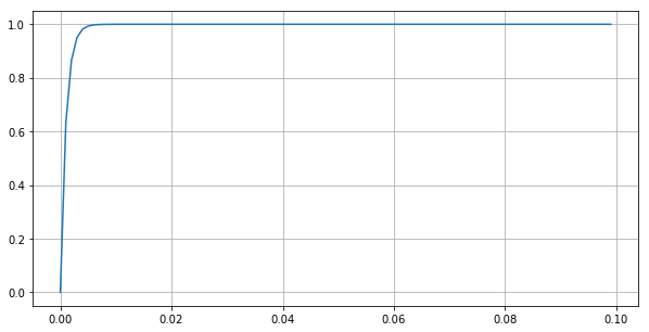
- rcstep1.png (6.83 KiB) Viewed 22857 times
It seemed this is still feasible as the RC step response is about 10 milliseconds, i.e. if the capacitor is initially discharged it charges to the original Vin voltages in 10 ms. But in this calc, I may have neglected the temperature sensor limits, which is 50 uA max. So the response may be significantly longer.
If I work the internal resistance of
LMT86, this way R = 2.2v / 50 uA ~ 44k ohms
putting R = 44k, C = 1.0 uF
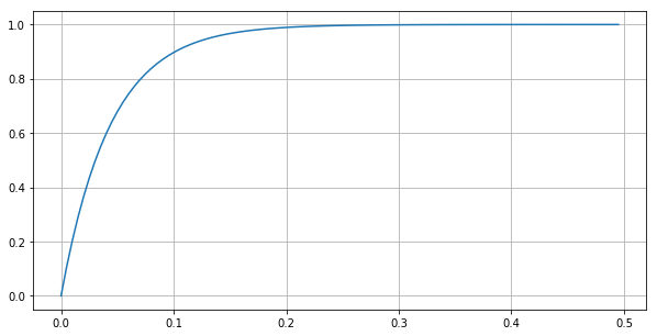
- rcstep1a.png (9.76 KiB) Viewed 22853 times
^ the step response looks like this. This is significantly worse than if it is just R 1K and C 1uF