Problems with SPI (Nucleo L476RG)
Posted: Wed Aug 03, 2022 9:16 pm
Hi,
I'm quite new to STM32 boards and figured I would start with STM32duino and get a good grasp of things before moving on to STM32Cube.
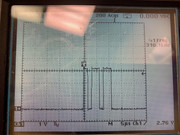
I have been struggling off and on now for the past few days to get SPI to work with my board and a magnetometer sensor (PNI RM3100). I found a sample sketch on GitHub that worked on my Arduino Nano with the following output:
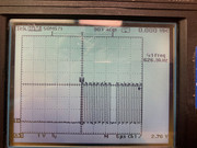
However, when connecting my Nucleo L476RG and uploading the same code I get this output (it looks like Rev ID and cycle count are reading max values for their respective value types of uint8_t and uint16_t):
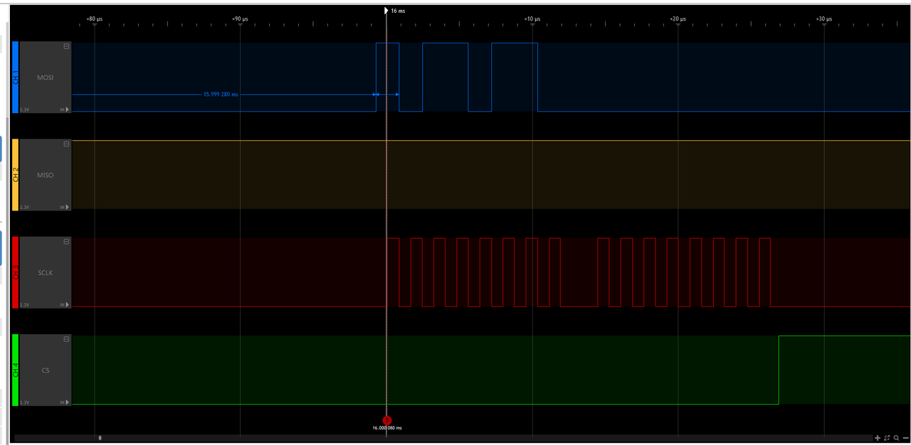
The pins I am using for my sensor are:
D9 - DRDY (DATA READY)
D10 - CS
D11 - MOSI
D12 - MISO
D13 - SCK
The rest being either GND, supply voltage, or not connected.
This is the sketch I am using:
For what it's worth I also tried using SPI with an ADXL345 (accelerometer). Again with a working sketch for an Arduino but getting no usable results on the STM32 board, so I imagine I'm missing something simple, but I've looked at a lot of different examples, looked over the datasheet for the sensor and I'm just coming up with nothing. I would appreciate any help..
I'm quite new to STM32 boards and figured I would start with STM32duino and get a good grasp of things before moving on to STM32Cube.
I have been struggling off and on now for the past few days to get SPI to work with my board and a magnetometer sensor (PNI RM3100). I found a sample sketch on GitHub that worked on my Arduino Nano with the following output:
Code: Select all
REVID ID = 0x22
Cycle Counts = 200
Gain = 74.92
Data in counts:   X:1662   Y:750   Z:2520
Data in microTesla(uT):   X:22.18   Y:10.01   Z:33.64
Magnitude(uT):41.52
Code: Select all
REVID ID = 0xFF
Cycle Counts = 65535
Gain = 24059.40
Data in counts:   X:-1   Y:-1   Z:-1
Data in microTesla(uT):   X:-0.00   Y:-0.00   Z:-0.00
Magnitude(uT):0.00
D9 - DRDY (DATA READY)
D10 - CS
D11 - MOSI
D12 - MISO
D13 - SCK
The rest being either GND, supply voltage, or not connected.
This is the sketch I am using:
Code: Select all
#include "SPI.h"
#include "Arduino.h"

//pin definitions
#define PIN_DRDY 9 //Set pin D9 to be the Data Ready Pin
#define PIN_CS 10 //Chip Select (SS) is set to Pin 10

//internal register values without the R/W bit
const int RM3100_REVID_REG = 0x36; // Hexadecimal address for the Revid internal register
const int RM3100_POLL_REG = 0x00; // Hexadecimal address for the Poll internal register
const int RM3100_CMM_REG = 0x01; // Hexadecimal address for the Continuous Measurement Mode internal register
const int RM3100_STATUS_REG = 0x34; // Hexadecimal address for the Status internal register
const int RM3100_CCX1_REG = 0x04; // Hexadecimal address for the Cycle Count X1 internal register
const int RM3100_CCX0_REG = 0x05; // Hexadecimal address for the Cycle Count X0 internal register

//options
#define initialCC 200 // Set the cycle count
#define singleMode 0 //0 = use continuous measurement mode; 1 = use single measurement mode
#define useDRDYPin 1 //0 = not using DRDYPin ; 1 = using DRDYPin to wait for data

uint8_t revid;
uint16_t cycleCount;
float gain;

void setup() {
  pinMode(PIN_DRDY, INPUT);
  pinMode(PIN_CS, OUTPUT);
  digitalWrite(PIN_CS, HIGH);
  SPI.begin(); // Initiate the SPI library
  SPI.beginTransaction(SPISettings(1000000, MSBFIRST, SPI_MODE0));
  Serial.begin(9600); //set baud rate to 9600
  delay(1000);

  revid = readReg(RM3100_REVID_REG);

  delay(1000);
  Serial.print("REVID ID = 0x"); //REVID ID should be 0x22
  Serial.println(revid, HEX);

  changeCycleCount(initialCC); //change the cycle count; default = 200 (lower cycle count = higher data rates but lower resolution)

  cycleCount = readReg(RM3100_CCX1_REG);
  cycleCount = (cycleCount << 8) | readReg(RM3100_CCX0_REG);

  Serial.print("Cycle Counts = "); //display cycle count
  Serial.println(cycleCount);

  gain = (0.3671 * (float)cycleCount) + 1.5; //linear equation to calculate the gain from cycle count

  Serial.print("Gain = "); //display gain; default gain should be around 75 for the default cycle count of 200
  Serial.println(gain);

  if (singleMode) {
    //set up single measurement mode
    writeReg(RM3100_CMM_REG, 0);
    writeReg(RM3100_POLL_REG, 0x70);
  }
  else {
    // Enable transmission to take continuous measurement with Alarm functions off
    writeReg(RM3100_CMM_REG, 0x79);
  }
}

void loop() {
  long x = 0;
  long y = 0;
  long z = 0;
  uint8_t x2, x1, x0, y2, y1, y0, z2, z1, z0;

  //wait until data is ready using 1 of two methods (chosen in options at top of code)
  if (useDRDYPin) {
    while (digitalRead(PIN_DRDY) == LOW); //check RDRY pin
  }
  else {
    while ((readReg(RM3100_STATUS_REG) & 0x80) != 0x80); //read internal status register
  }

  //read measurements
  digitalWrite(PIN_CS, LOW);
  delay(100);
  SPI.transfer(0xA4);
  x2 = SPI.transfer(0xA5);
  x1 = SPI.transfer(0xA6);
  x0 = SPI.transfer(0xA7);

  y2 = SPI.transfer(0xA8);
  y1 = SPI.transfer(0xA9);
  y0 = SPI.transfer(0xAA);

  z2 = SPI.transfer(0xAB);
  z1 = SPI.transfer(0xAC);
  z0 = SPI.transfer(0);

  digitalWrite(PIN_CS, HIGH);

  //special bit manipulation since there is not a 24 bit signed int data type
  if (x2 & 0x80) {
    x = 0xFF;
  }
  if (y2 & 0x80) {
    y = 0xFF;
  }
  if (z2 & 0x80) {
    z = 0xFF;
  }

  //format results into single 32 bit signed value
  x = (x * 256 * 256 * 256) | (int32_t)(x2) * 256 * 256 | (uint16_t)(x1) * 256 | x0;
  y = (y * 256 * 256 * 256) | (int32_t)(y2) * 256 * 256 | (uint16_t)(y1) * 256 | y0;
  z = (z * 256 * 256 * 256) | (int32_t)(z2) * 256 * 256 | (uint16_t)(z1) * 256 | z0;

  //calculate magnitude of results
  double uT = sqrt(pow(((float)(x) / gain), 2) + pow(((float)(y) / gain), 2) + pow(((float)(z) / gain), 2));

  //display results
  Serial.print("Data in counts:");
  Serial.print("   X:");
  Serial.print(x);
  Serial.print("   Y:");
  Serial.print(y);
  Serial.print("   Z:");
  Serial.println(z);

  Serial.print("Data in microTesla(uT):");
  Serial.print("   X:");
  Serial.print((float)(x) / gain);
  Serial.print("   Y:");
  Serial.print((float)(y) / gain);
  Serial.print("   Z:");
  Serial.println((float)(z) / gain);

  //Magnitude should be around 45 uT (+/- 15 uT)
  Serial.print("Magnitude(uT):");
  Serial.println(uT);
  Serial.println();
  delay(1000);
}

//addr is the 7 bit value of the register's address (without the R/W bit)
uint8_t readReg(uint8_t addr) {
  uint8_t data = 0;
  digitalWrite(PIN_CS, LOW);
  delay(100);
  SPI.transfer(addr | 0x80); //OR with 0x80 to make first bit(read/write bit) high for read
  data = SPI.transfer(0);
  digitalWrite(PIN_CS, HIGH);
  return data;
}

//addr is the 7 bit (No r/w bit) value of the internal register's address, data is 8 bit data being written
void writeReg(uint8_t addr, uint8_t data) {
  digitalWrite(PIN_CS, LOW);
  delay(100);
  SPI.transfer(addr & 0x7F); //AND with 0x7F to make first bit(read/write bit) low for write
  SPI.transfer(data);
  digitalWrite(PIN_CS, HIGH);
}

//newCC is the new cycle count value (16 bits) to change the data acquisition
void changeCycleCount(uint16_t newCC) {
  uint8_t CCMSB = (newCC & 0xFF00) >> 8; //get the most significant byte
  uint8_t CCLSB = newCC & 0xFF; //get the least significant byte

  digitalWrite(PIN_CS, LOW);
  delay(100);
  SPI.transfer(RM3100_CCX1_REG & 0x7F); //AND with 0x7F to make first bit(read/write bit) low for write
  SPI.transfer(CCMSB);  //write new cycle count to ccx1
  SPI.transfer(CCLSB);  //write new cycle count to ccx0
  SPI.transfer(CCMSB);  //write new cycle count to ccy1
  SPI.transfer(CCLSB);  //write new cycle count to ccy0
  SPI.transfer(CCMSB);  //write new cycle count to ccz1
  SPI.transfer(CCLSB);  //write new cycle count to ccz0
  digitalWrite(PIN_CS, HIGH);
}