herbk wrote: Mon Sep 05, 2022 5:27 pm
Thank you all for the Infos, it eliminates my concerns that every sketch grows 10 times...

the binaries tend to stay around "similar" sizes for an 'average' sketch, it is "fat" for a particular bundle e.g. if you include the "normal" usb-(cdc)-serial, it may take say 20-30k, but later the 'growth' between 20-60k would be slower, as that depends on your sketch (that is).
the 'official' core
https://github.com/stm32duino/Arduino_Core_STM32
tends to be somewhat a little more bloat as it tries to do a lot of things, which includes trying to cater to pretty much the whole stm32 series.
i.e. it support *a lot of* chips, you can take a look at the boards list on the core repository page.
and on top, it tries to bundle all the basic things (analog analogRead/analogWrite, gpio digitalRead,digitalWrite, uart, etc), FPU (single precision floating point hardware) if you use the stm32f4xx series (this is 'a lot' faster vs stm32f103 if codes run with single precision floating point calcs are benchmarked).
Inevitably, the linker may not be able to figure out too many dependencies and it could include a little extra bloat rather than to leave it out and your sketch may crash, missing dependency.
Hence, get a board/chip that has a 'comfortable' amount of flash and sram. e.g. at least 64k flash and 20k sram (this is quite cramp literally) - that would be for the stm32f103 c8 blue pill based boards. a f103 c6 based board/chip may run out of flash or sram too soon.
And things like that Nucleo F401 RE and F411 RE, normally has like 256-512k flash and like 64K sram (or more I think the specs for RE is 96 K sram).
even things like that 'F401 or F411 blackpill' (it needs to be CC or CE suffix) has like 128-256k flash and 64k sram, and it has that FPU.
This would be so much room, you probably can run pretty 'bulky' apps in it like micropython etc and it'd still dance.
"Ordinary" sketches would then use so little of that resource that you can literally throw many things at it.
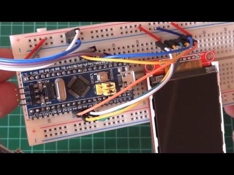
Add an LCD library (e.g. Adafruit ILI9341) (this is a huge one), throw in a few more libraries (add SPI), sensors (add Wire (i2c), and SD card + Fat FS library (this is another huge one), add usb-(CDC)-serial, add uart (Serial), play with Hardware Timers, add a big sketch to multitask between them, and you would likely still have spare flash and sram. It probably feels like there is 'megabytes' of it when it is only perhaps 128k flash and 64k sram.
I think something like a chip with RE in suffix 512k flash 96k sram is probably enough to fit the whole marlin firmware 2.0
https://marlinfw.org/
or even micropython
https://micropython.org/
or circuit python etc
https://circuitpython.org/
but for those 'huge' apps, they may even exhaust 512k flash and 96k sram, but more than likely the 'smaller' configs can fit and run a 3d printer.
that could depend on the feature set 'configured', e.g. to add lots of fancy features + wifi (say add a esp8266 dongle - ESP-01) + web server etc 96k sram could be 'too cramped'
Disabling unneedet features sounds good, - i think it helps save energie to, - true ?
not really,
this is for the 'advanced' tinkerers:
stm32 has many peripherals (uart, spi, timers, i2c, gpio banks etc), if you don't clock them they save power, but they are *switched off* if you don't clock them. and for most stm32 chips you can play with and vary the system clocks, under clock, over clock, whatever you please.
Now i first have to figure out where are the differences between the Arduinos and the STMs, e.g. where ( and what) do i need to change the Sketches. Questins to that:
How can I address the pins, is there the need to define a analog pin for input or 5V or 3.3V... it has both pins... ?
Is there somewhere a tutorial für the STMs ( e.g. like the Arduino Reference ) ?
stm32 pins are named after the PAxx, PBxx, PCxx etc definitions according to their specs sheet.
e.g. for some 'pill' boards, they put the led at PC13, and it is active low. check the schematics for your board.
so lighting up the led is
Code: Select all
void setup() {
	pinMode(PC13, OUTPUT);
}

void loop() {
	digitalWrite(PC13, LOW); // turn on led, active low
	delay(10);
	digitalWrite(PC13, HIGH); // turn off led
	delay(10);
}
all stm32 pins are 3.3v, the analog (e.g. ADC) pins normally can only do 3.3v, but some gpio pins can tolerate 5v.
you need check the specs sheet for your chip part number
e.g. for stm32f103c8
https://www.st.com/resource/en/datashee ... f103c8.pdf
and the reference manual is this
https://www.st.com/resource/en/referenc ... ronics.pdf
and do review the wiki if you are running the 'official' core.
https://github.com/stm32duino/wiki/wiki
here are some "samples"
https://github.com/stm32duino/STM32Examples
and in the wiki
https://github.com/stm32duino/wiki/wiki
and the api reference
https://github.com/stm32duino/wiki/wiki/API