Page 1 of 3
STM32C011 (WeAct) - first steps
Posted: Tue May 07, 2024 8:29 pm
by STM32ardui
Today my
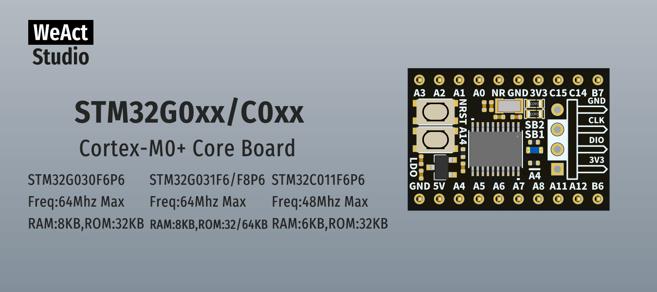
STM32C011F6P6-boards from WeAct Studio arrived.
As you can see from this
picture they don't USB connector, but the 4 pins GND, CLK, DIO, 3V3 for a ST-Link. At the moment I don't have one at home. So can I upload a program also with a USB to UART-adapter like I made it with a BlackPill-board?
So I look around the documentation ...
STM32C0x1 Reference Manual, chapter 2.5 Boot configuration, page 46:
Code: Select all
Embedded boot loader
The embedded boot loader is located in the System memory, programmed by ST during
production. It is used to reprogram the Flash memory using one of the following serial
interfaces:
• USART1
• I2C1
For further details, refer to the device data sheets and the application note AN2606.
Code: Select all
USART1 Enabled Once initialized, the USART1 configuration is 8 bits, even parity, and one stop bit.
USART1_RX pin Input PA10 pin: USART1 in reception mode. Used in input pull-up mode.
USART1_TX pin Output PA9 pin: USART1 in transmission mode. Used in alternate push-pull, pull-up mod
page 27 Fig. 5 shows pinout in TSSOP20 package:
- 17 PA12[PA10]
- 16 PA11[PA9]
Also table 12 on page 29 contains in column "function upon reset" for TSSOP20:
- 16 PA11 [PA9]
- 17 PA12[PA10]
I don't know the meaning of such double numbering, but I think, these pins are the serial interface?
Bye, Jürgen
Windows 10
ArduinoIDE 2.3.2 (as portable version)
with Platform STMicroelectronics:stm32@2.7.1
Re: STM32C011 (WeAct) - first step
Posted: Wed May 08, 2024 4:01 pm
by STM32ardui
WeAct Studio placed a demo on the STM32C011-board. The LED at PA4 flashes and with a connection from UART1 (PA11/PA12) via adapter to PC, I can see a kind of timestamps in a terminal program (115200 baud):
Code: Select all
2023.01.01 00:01 24
2023.01.01 00:01 25
2023.01.01 00:01 26
2023.01.01 00:01 27
...
But it seems to be impossible to use UART1 for programming.
For a STM32F411CEU6 the AN2606 says
pattern 1: Boot0(pin) = 1 and Boot1(pin) = 0
So that's what you're doing by holding BOOT0 down, press NRST and release them again?
STM32C011 has
pattern 11:
nBoot0(bit) = 0, nBoot1(bit) = 1, nBOOT0_SEL(bit) = 1 and BOOT_LOCK(bit) = 0
Boot0(pin) = 1, nBoot1(bit) = 1, BOOT_LOCK(bit) = 0 and nBOOT0_SEL (bit) = 0
nBoot0(bit) = 1, nBOOT0_SEL(bit) = 1, BOOT_LOCK(bit) = 0 and main flash memory empty
Boot0(pin) = 0, nBOOT0_SEL(bit) = 0, BOOT_LOCK(bit) = 0 and main flash memory empty
I read something about "option byte", but don't know exactly the meaning.
Also I don't know, if the behavior comes from the demo and a fresh chip can be programmed via UART1.
I found an old Waveshare ST-Link V2 Mini. After a firmware upgrade STM32CubeProgrammer gets a connect. In the log I see:
Code: Select all
  17:25:22 : Voltage     : 3.25V
  17:25:22 : SWD freq    : 4000 KHz
  17:25:22 : Connect mode: Normal
  17:25:22 : Reset mode  : Software reset
  17:25:22 : Device ID   : 0x443
  17:25:22 : Revision ID : Rev A
  17:25:22 : Debug in Low Power mode is not supported for this device.
  17:25:22 : UPLOADING OPTION BYTES DATA ...
  17:25:22 :   Bank          : 0x00
  17:25:22 :   Address       : 0x40022020
  17:25:22 :   Size          : 100 Bytes
  17:25:22 : UPLOADING ...
  17:25:22 :   Size          : 1024 Bytes
  17:25:22 :   Address       : 0x8000000
  17:25:22 : Read progress:
  17:25:22 : Data read successfully
So STM32CubeProgrammer resets those "option byte(s)"?
Bye, Jürgen
Re: STM32C011 (WeAct) - first step
Posted: Sat May 11, 2024 2:41 pm
by trimarco232
Hi Jürgen ,
imho. :
- (STM32G030F6P6 had been a better choice)
- you rather continue to use your programmer for devices without USB , so you don't worry about BOOT0
- PA9 & PA10 can't be used out of the box for bootloader , because they are not connected to the pins by default ; may be you can use I2C1 for bootloader
Re: STM32C011 (WeAct) - first steps
Posted: Wed May 15, 2024 1:18 pm
by STM32ardui
Thank's for your answer, Trimarco.
I wanted a small and cheap board, so I bought some STM32C011. STM32G030F6P6 has 2 kB RAM more and can run at 64 MHz instead 48 MHz. That's not so important for me.
Until now I used some Arduino, ESP8266/ESP32 and SAMD21-boards. So using a STLink is new for me. But it works and I have nothing to complain ... ok, nearly nothing.
If I send information by Serial.print(), I can't see it over STLink-connection?
I still need a USB to Serial-adapter?
It looks like I can have both connected to the STM32C011 and only take off USB-cable from ST-Link and connect it to USB to Serial-adapter.
BTW: I'm surprised, that millis() also work with STM32-boards

I thought I have to use HAL_GetTick().
Re: STM32C011 (WeAct) - first steps
Posted: Wed May 15, 2024 8:16 pm
by trimarco232
If I send information by Serial.print(), I can't see it over STLink-connection?
I still need a USB to Serial-adapter?
STLink can't handle serial (UART like) signals , so :
- yes , use a USB to Serial-adapter
- or a DAPLink (if it works with arduino ?)
- or , if your informations are for debug , use the debug capability of the arduino IDE (never tried it too)
please let us now !
Re: STM32C011 (WeAct) - first steps
Posted: Thu May 16, 2024 7:41 am
by STM32ardui
At the moment I don't want to debug code with ArduinoIDE.
If I connect for example a sensor to a STM32-board, I want to see the output in serial monitor of ArduinoIDE.
STLink and USB-TTL-adapter both have a USB-A male plug. So I use an extension cord with USB-A female plug on one side. I connect it with STLink for uploading and afterwards with USB-TTL-adapter to see output. Looks like they don't disturb each other.
Such a DAPLink has SWDIO/SWDCLK and TX/RX, so I can connect it to both interfaces but I need only one USB-connection to the computer? May be I will buy one and try it with ArduinoIDE ...
Re: STM32C011 (WeAct) - first steps
Posted: Thu May 16, 2024 9:36 pm
by trimarco232
- you rather use a terminal emulator in order to see your outputs , so you do no more need to plug/unplug
- DAPLink is for MBed , and will work for other IDEs , but for Arduino , I really fear it won't work , so far
Re: STM32C011 (WeAct) - first steps
Posted: Fri May 17, 2024 7:31 am
by STM32ardui
trimarco232 wrote: Thu May 16, 2024 9:36 pm
- DAPLink is for MBed , and will work for other IDEs , but for Arduino , I really fear it won't work , so far
I think the problem is, that ArduinoIDE started with 8bit microcontroller.
And debugging is a new topic since IDE 2.x comes out.
In
documentation I found:
Arduino® boards with a SAMD microcontroller feature native on-chip debug capabilities; these debugging capabilities can be used with an external ICD tool over JTAG or SWD interfaces. CMSIS-DAP compliant debug probes can be used with the Arduino IDE 2 out of the box without any configuration file; non-standard debug probes require a special configuration. Check out these tutorials to learn how to use an external ICD tool with SAMD based Arduino boards and the Arduino IDE 2:
Debugging with the SEGGER J-Link.
Debugging with the Atmel-ICE.
Otherwise there is poor information about ArduinoIDE and DAP-Link.
So I ordered a part and will see at the end of the month, if it will work ...
Re: STM32C011 (WeAct) - first steps
Posted: Fri May 17, 2024 8:19 am
by STM32ardui
What drives me crazy at the moment is I²C 
Generally information is spread over several places. I know there are STM32Examples, but there is nothing about I²C. Instead you have to look at Arduino_Core_STM32/libraries/Wire/ And for some additional information, you have to look at:
https://github.com/stm32duino/Arduino_C ... ki/API#i2C
There I found:
By default, only one Wire instance is available and it uses the Arduino pins D14(SDA) and D15(SCL)

STM32-boards have GPIOs named PA
nn, PB
nn or PC
nn - but I never seen D14/D15 on a STM32-board.
For my project I don't need I²C on the little STM32C011F6P6. But I want to know, if there is a I²C interface right from powering up. I want to try a BH1750 sensor. It works on an ESP32, so there is no problem with pull up resistors and I know the I²C-address.
I tried it on PB6/PB7, but the I2scanner.ino tells me, there is not I²c-device.
I tried it this way:
Code: Select all
Wire.setSDA(PA5);
Wire.setSCL(PA4);
Wire.begin();
Now I2scanner.ino comes out with "unknown error" for each possible address.
I also look inside PeripheralPins.c for my board:
Code: Select all
#ifdef HAL_I2C_MODULE_ENABLED
WEAK const PinMap PinMap_I2C_SDA[] = {
  {PA_10_R, I2C1, STM_PIN_DATA(STM_MODE_AF_OD, GPIO_NOPULL, GPIO_AF6_I2C1)},
  {PB_7,    I2C1, STM_PIN_DATA(STM_MODE_AF_OD, GPIO_NOPULL, GPIO_AF6_I2C1)},
  {PC_14,   I2C1, STM_PIN_DATA(STM_MODE_AF_OD, GPIO_NOPULL, GPIO_AF14_I2C1)},
  {NC,      NP,   0}
};
#endif
Three different pins?
Which is the right one???
And what means PA_10_R? I know my board don't have PA9/PA10. Inside datasheet is some crypted info about PA11/PA12 ... stand "R" for replace or remap?
Re: STM32C011 (WeAct) - first steps
Posted: Fri May 17, 2024 10:03 am
by trimarco232