
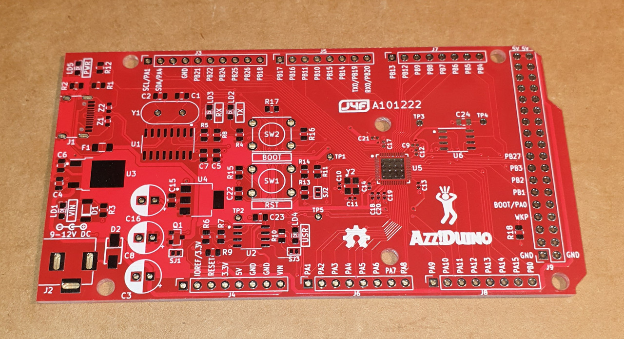
The PCB allows two options: PSRAM and external 9-12V supply.
I've just soldered a first board (no option installed) and it seems work as expected:
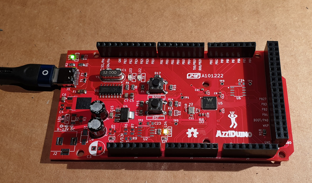
I'll publish all the details when ready, just in case...
Code: Select all
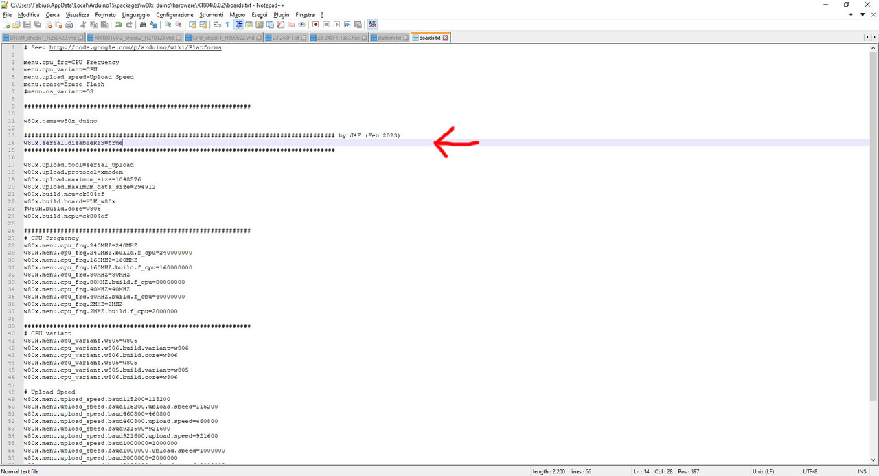
tools.serial_upload.upload.pattern="{cmd.path}" {upload.params.verbose} {serial.port} -ws 115200 -ds {upload.speed} -dl "{build.path}/{build.project_name}.fls"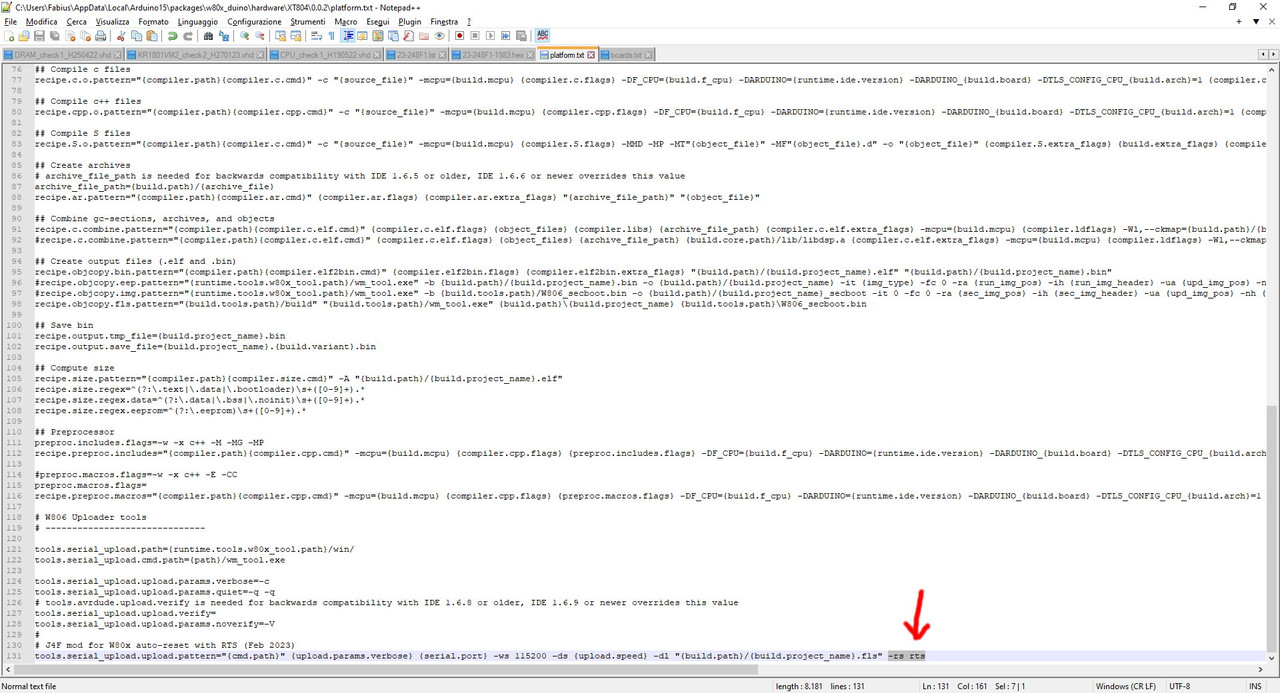
I ran the same code on a STM32F103.I am going to manually calibrate a STM32F103 chip to see how that works.
my 5-min attempt at thisyou should be able to write a piece of code to find the optimal HSITRIM value
Code: Select all
//tune LSI frequency
//Ftgt: the target frequency used to tune LSI
//return: the calculated F_LSI
uint32_t LSItune(uint32_t Ftgt) {
	uint8_t cnt=0;						//tycle counter
	uint32_t flsi_now=F_LSI, flsi_last;			//initialize flsi
	uint32_t ftgt=Ftgt;
	uint32_t tmp;

	do {
#if 1											//for debugging
		//for debug only
		//display the frequency
		tmp = flsi_now;							//item to be displayed
		tmp = tmp % 10000;						//display the last four digits
		//tmp = (tmp / 10000) % 10000;			//display the first four digits
		lRAM[3]=tmp % 10; tmp /=10;
		lRAM[2]=tmp % 10; tmp /=10;
		lRAM[1]=tmp % 10; tmp /=10;
		lRAM[0]=tmp % 10; tmp /=10;
		//end display
#endif
		flsi_last=flsi_now;						//update flsi
		rtcInit(RCC_BDCR_RTCSEL_LSI, flsi_last);	//initialize the rtc
		ftgt=rtcTicks(4)/4;						//average ftgt over a period of time
		flsi_now=Ftgt * flsi_last / ftgt;		//update the new flsi
		if (flsi_now==flsi_last) break;		//exit if two consecutive measurements are the same
	} while (cnt++<16);							//exit for overtime
	return flsi_now;
}
